Pilot to Production; Your Medical Extrusion and Cable Partner.
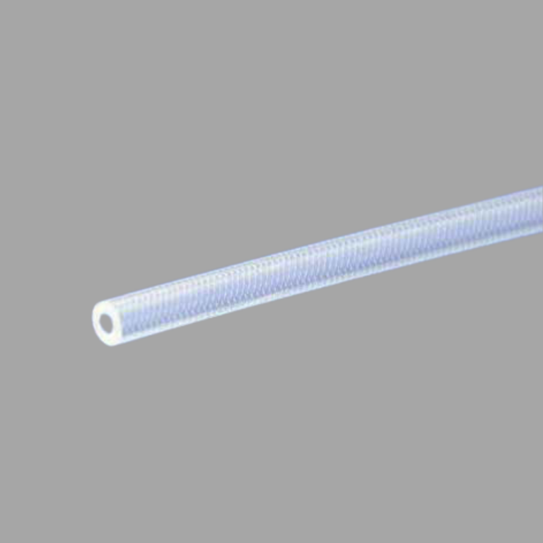
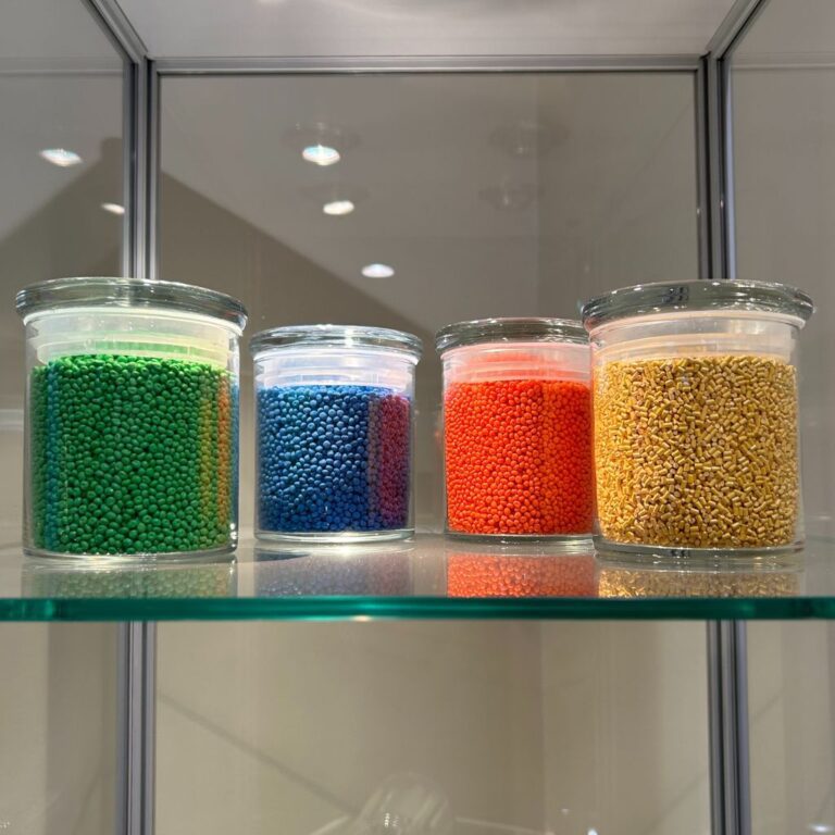
HPMS is a global contract manufacturer for Medical OEMs worldwide. With over 20 years of experience in the OEM value stream, we are dedicated to providing complete in-house medical tubing and cable solutions for surgical, catheter, endoscopy and ultrasound markets. Medical wire and tubing are vital components to many critical, life-saving devices.
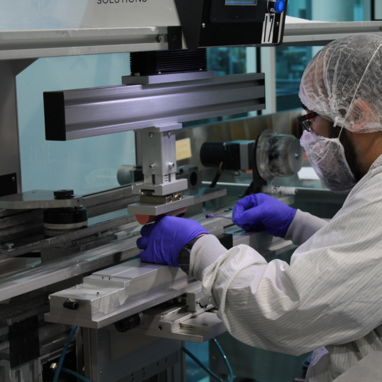
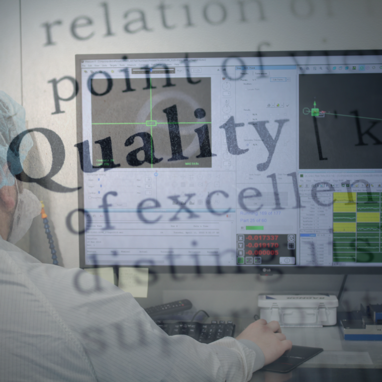
We offer unrivaled expertise and vertical integration. At HPMS, we have over 30,000sq ft of ISO Class 8 and ISO Class 9 cleanrooms. We ensure exceptional quality and compliance for every finished medical device component. Choose us for reliable and efficient contract manufacturing solutions.